This weekend I finally bought a membership for the QC Co-Lab, and took the opportunity to work on the TV Tuner modification I talked about previously.
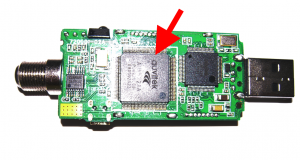
Again, it’s a Hauppauge WinTV-HVR-950Q that I got from Newegg, and while I was using it, I noticed the main chip was getting hot. Â While I can’t claim it had any noticable impact on image quality or performance, I just wasn’t comfortable with the casing becoming too hot to touch. Â So I removed the casing and started watching TV to see which chip heated up. Â That chip is pointed out here:
Looking up the chip, it’s an Auvitek AU8522AA, the ATSC / NTSC decoder for the incoming signal. It makes sense that it would get so hot. Â So the next step is to order the heatsinks, I chose these from Newegg. Once I had those, I tested them on the bare TV Tuner, and found I actually needed two:
While the larger chip was generating the majority of the heat, the smaller one heated up pretty well too. Â Also, ideally I would’ve bought two sets of heatsinks, a larger set for the main chip, and then used the ones I have for the smaller chip. Â But at $15 for these heatsinks, I wasn’t willing to spend more.
Next up was marking the casing for the holes. Â Originally I had planned on using a stamp ink pad to mark the pins, and press that against the casing to determine where the holes should go. Â I forgot to buy one, so I had to improvise on site with some thermal grease.
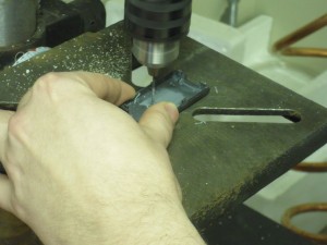
While I was discussing this with my friend Ben, he enthusiastically volunteered to start the drilling, so I took the chance for another picture:
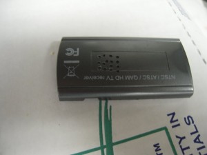
Unfortunately that drill has a bit of vibration on it. Â So the holes didn’t line up with the precision we were hoping for:
Not a problem, I just cleared out a larger hole to fit the entire heatsink through.
On the second set of holes, I marked through the thermal grease with some marker to help line things up. Â The drill still had a lot of give though, so it wasn’t going to line up properly. Â I had to re-drill the same holes several times before the entire heatsink would fit through.
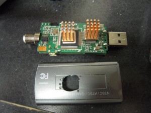
I’m so happy that I got this shot, when I was mentally picturing this project, this is what I wanted. Â Individual openings for each heatsink rod, with space inbetween to keep it inside and pressed onto the chip.
Unfortunately, the bases on the heatsink were taller than I expected, and I couldn’t fit the entire casing back on with the openings done this way. Â So the second heatsink has a full opening like the first one. Â Here is the final result, after I swapped the marked heat sinks for fresh ones:
While this definitely looks home made, I think it still looks clean and presentable.
As for the results of the mod: Â Over time, the entire casing can still get pretty hot, the heatsinks themselves get too hot to touch after about an hour of watching or so. Â Performance is effectively unchanged, since it was working correctly before this modification, but I’m much more comfortable with it knowing the heatsinks are pulling away a lot of that heat.
And also, if you want to see some other QC Co-Lab pictures, they are available in this Picasa album: http://goo.gl/USaNb
Thanks for reading!


This is great! I’ve always liked heatsinks – I try to save the heatsink whenever I throw a computer in a skip as a kind of memento to help preserve all the memories associated with the box.